

|
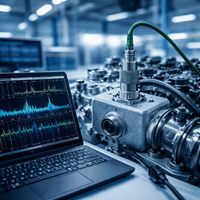
Acceleration is the rate at which the velocity of an object changes over time. Mathematically, it is the derivative of the velocity vector with respect to time, expressed as a = dv/dt. Acceleration is the net result of all forces acting on an object. In measurement practice, acceleration is usually considered in two main ways. The first is acceleration caused by vibration of the test object. The second is acceleration caused by changes in motion, such as the acceleration, braking, or cornering of a vehicle or aircraft. These two measurement objectives require very different sensor behavior. In vibration measurement, the dynamic part of the signal is the key information. In vehicle dynamics and motion measurements, the sensor must be able to measure static acceleration, including the effect of gravity. |
|
Basic Types of Acceleration MeasurementsTo support different applications, acceleration measurements are commonly grouped into the following categories:
In many applications, acceleration is also used to derive velocity and displacement through integration. Conversely, acceleration can sometimes be derived mathematically from velocity or displacement signals, for example when using laser displacement sensors or eddy current probes. |
Video introduction to acceleration measurement |
The Relationship Between Acceleration, Velocity, and DisplacementVelocity is the derivative of displacement with respect to time, expressed as v = ds/dt. Acceleration is the derivative of velocity, and it is also the second derivative of displacement. This makes the three quantities closely linked in dynamic measurement systems. When integrating acceleration signals in vehicle or motion analysis, the static acceleration component leads to changes in calculated velocity and displacement. However, even small errors in acceleration measurements can accumulate into larger errors in velocity and distance. The size of this drift depends heavily on sensor quality and compensation techniques. In practice, users often combine accelerometers with other sensors such as rate gyros and GPS to improve accuracy. In vibration measurements, the static component is not important and is usually removed with high-pass filtering before integration. |
|
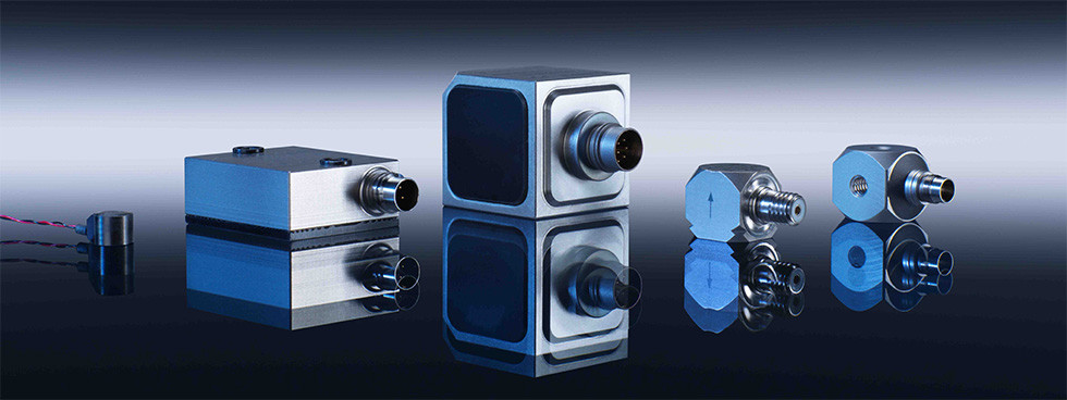
What Is an Accelerometer?An accelerometer is a sensor that produces an electrical signal corresponding to the acceleration it experiences. Depending on the sensing principle, the output may be in the form of voltage, charge, or another electrical quantity. There are several ways to convert acceleration into an electrical signal. Each technology has its own advantages, limitations, and ideal application range. The right sensor choice depends on required frequency range, amplitude range, environment, DC response, sensitivity, and durability. |
|
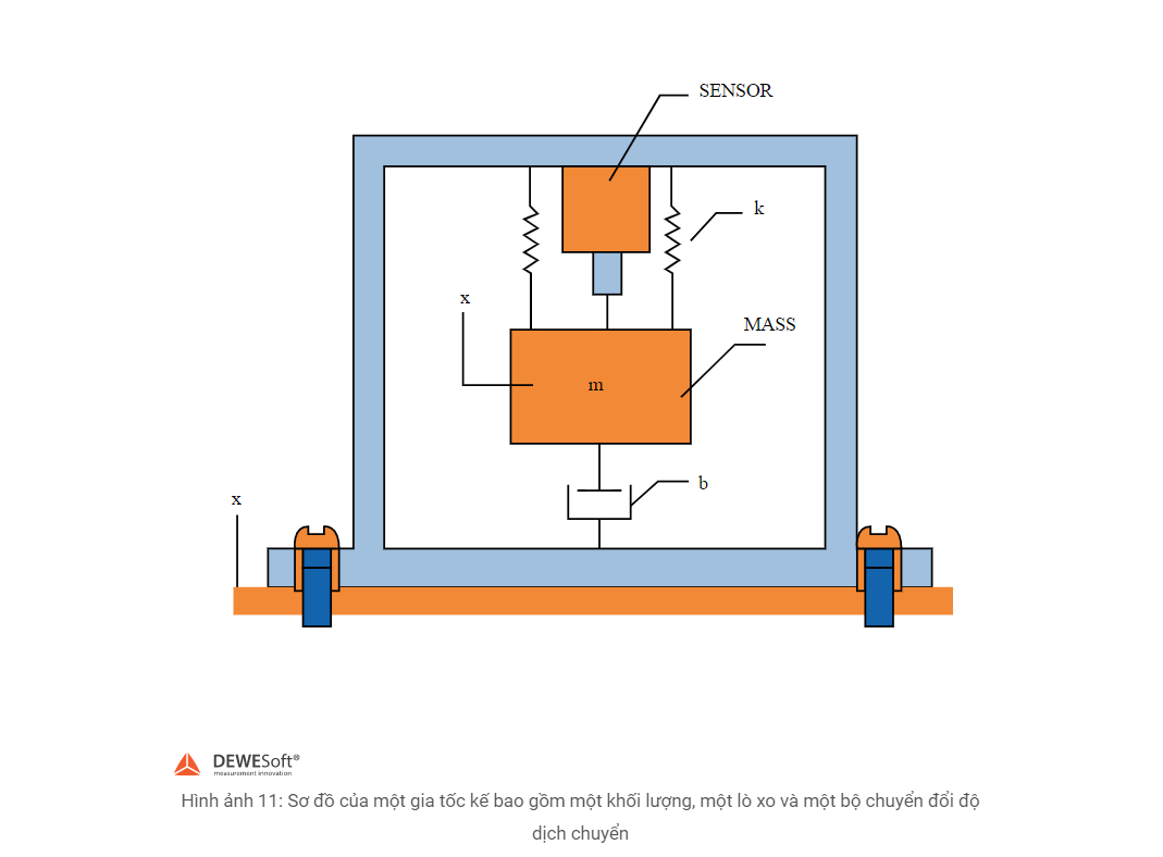
Basic Working Principle of AccelerometersMost accelerometers are based on Hooke’s law and Newton’s laws of motion. Hooke’s law states that the force required to stretch or compress a spring is proportional to the displacement, expressed as F = k × x, where k is the spring constant and x is the displacement. Newton’s second law states that force is equal to mass times acceleration, expressed as F = m × a. Combining these two principles, a typical accelerometer includes a seismic mass, a spring or equivalent mechanical suspension, and a displacement transducer. When the sensor housing moves, the inertial mass resists the motion. The relative displacement between the mass and the frame is measured and converted into an electrical signal proportional to acceleration. |
|
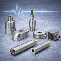
Common Types of AccelerometersAccelerometers can be designed using several different sensing principles. The most common types include:
|
|
|
Video introduction to accelerometer types |
Why sensor selection mattersChoosing the right accelerometer technology is important because each type is optimized for different signals and environments. Some applications require wide-band vibration measurements, some require very high shock capability, and others need true static acceleration and low-frequency motion response. That is why understanding the differences between IEPE, charge, MEMS, and piezoresistive sensors is essential for building an accurate and reliable measurement system. |
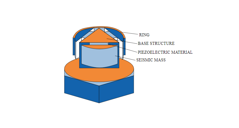
Piezoelectric AccelerometersPiezoelectric accelerometers are among the most widely used sensors for vibration measurements. They work based on the ability of piezoelectric materials such as quartz, tourmaline, piezoelectric ceramics, and other specialized materials to generate charge when subjected to mechanical stress. When the seismic mass applies force to the piezoelectric element, the sensor generates an electrical signal proportional to the experienced acceleration. These sensors offer major advantages such as wide frequency response, high durability, good linearity, compact size, and excellent suitability for modal testing, vibration testing, flight testing, predictive maintenance, and machine condition monitoring. However, piezoelectric accelerometers are not suitable for measuring static acceleration or long-term DC signals. They are therefore mainly used for dynamic events such as vibration and shock. |
Typical Applications
|
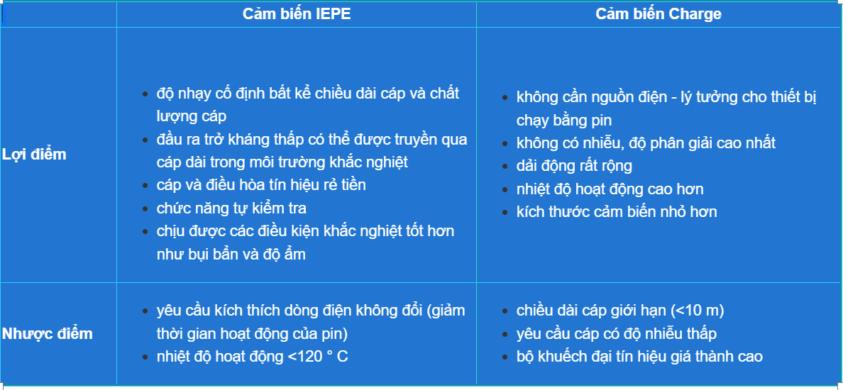
IEPE AccelerometersIEPE accelerometers are piezoelectric sensors with built-in electronics that convert the high-impedance charge signal into a low-impedance voltage output. These sensors are powered by a constant current supply over a simple two-wire configuration. Because of their low-impedance output, IEPE sensors are easier to use over longer cable runs, offer better noise immunity, and integrate easily with modern DAQ systems. They also tend to be more convenient and cost-effective for general vibration measurement setups than charge sensors. IEPE accelerometers are commonly used in general vibration testing, machine condition monitoring, NVH, modal analysis, and a wide range of industrial applications. Their main limitation is that they do not measure DC and usually have lower extreme shock capability than charge-mode sensors. |
Charge AccelerometersUnlike IEPE sensors, charge accelerometers output a raw charge signal directly from the piezoelectric element and do not include built-in conversion electronics. Because the charge signal has very high impedance, it is highly sensitive to environmental noise and requires specialized low-noise cables and an external charge amplifier. The major advantages of charge accelerometers are their suitability for high-temperature environments and their ability to measure very large dynamic events, including extreme shock levels reaching thousands of g. They are often chosen for harsh environments, high-temperature testing, and specialized shock applications. Like IEPE sensors, charge accelerometers do not measure DC acceleration and are intended for dynamic signals only. |
|
|
IEPE vs Charge AccelerometersBoth IEPE and charge sensors are piezoelectric accelerometers, but they serve slightly different needs:
The right choice depends on the application environment, cable length, required acceleration range, temperature conditions, and signal conditioning requirements.
|
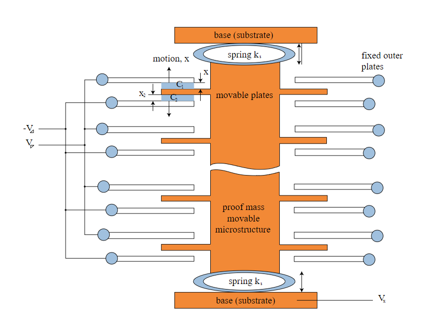
Static Accelerometers - MEMS SensorsBoth IEPE and charge accelerometers share one important limitation: they cannot measure static acceleration. They typically begin operating from around 0.3 Hz to several hertz, depending on the sensor design. For static or very low-frequency measurements, users typically choose MEMS accelerometers. These sensors offer good sensitivity and are suitable for DC response, slow motion, vehicle dynamics, tilt, braking, cornering, and inertial measurement applications. A typical MEMS accelerometer includes a tiny movable proof mass suspended inside a micro-mechanical structure. When acceleration is applied, the relative position between the mass and the reference structure changes, causing a change in capacitance or another electrical property that is then converted into the sensor output. MEMS accelerometers are now widely used in automotive systems, consumer electronics, inertial navigation, motion tracking, and many industrial applications that require static or low-frequency acceleration measurements. |
|
Which Accelerometer Should You Use?
Choosing the right accelerometer directly affects measurement quality as well as the accuracy of derived velocity, displacement, vibration, and dynamic behavior analysis. SummaryAcceleration is a fundamental quantity in many modern measurement applications, from vibration, shock, and vehicle motion to inertial systems and structural monitoring. Accelerometers are built using several sensing principles, with piezoelectric and MEMS technologies being among the most common. If the goal is wide-band dynamic vibration measurement, IEPE and charge sensors are powerful options. If static acceleration, slow motion, or DC response is required, MEMS sensors are usually the better solution. When combined with the right DAQ system and analysis software, the right accelerometer delivers accurate and reliable measurement data for a wide range of testing applications. |
|