

|
In this article, we will discuss TEDS sensor technology as defined by IEEE 1451. By the end of this article, you will:
Are you ready to get started? Let’s go. |
|
|
TEDS stands for Transducer Electronic Data Sheet. It is an EEPROM device embedded inside a sensor or sensor connector that stores information such as serial number, calibration date, and calibration factors. TEDS was introduced under IEEE P1451 as a standardized way of storing key information about probes, sensors, and actuators. TEDS enables true plug-and-play behavior for sensors, eliminating some or all manual setup steps and ensuring that the correct settings are applied automatically. This is why TEDS-enabled devices are often referred to as smart sensors. |
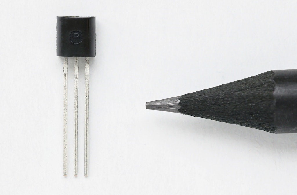
TEDS chip DS2431 |
|
Imagine a very small EEPROM installed inside the sensor or inside its connector, containing information such as:
The measurement system can read this information as soon as the sensor is connected, significantly simplifying sensor setup. TEDS was developed by the Institute of Electrical and Electronics Engineers (IEEE) as part of its smart transducer standard for sensors and actuators. The standard defines the digital communication protocol for reading and writing data to the sensor. For more technical detail, refer to IEEE Std 1451.4 (2004), often simply referred to as IEEE 1451. Because it is an open standard, TEDS devices are designed to be cross-platform and interchangeable regardless of manufacturer. |
|
Types of TEDS devicesThere are two main types of IEEE 1451.4 TEDS devices:
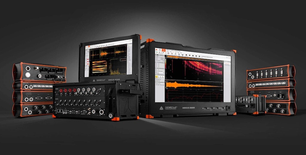
The flexibility of TEDS is clearly demonstrated by its support for both mixed-mode communication methods. Dewesoft DAQ systems can read both TEDS sensor types. Explore Dewesoft’s modern data acquisition systems with full TEDS compatibility. |
|
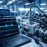
What is the purpose of TEDS?Imagine you are a test engineer setting up a modal test. You need to connect 100 accelerometers to a measurement system. Once the physical wiring is complete, you still have to open the DAQ software and configure each sensor manually by selecting gain, entering engineering units, applying scaling, entering compensation values, naming channels, and so on. This process can take hours because it requires constant cross-checking between individual sensor datasheets and the DAQ software. In many cases, you also have to trace sensor cables physically to make sure that no channels have been mixed up. This type of manual work is time-consuming, expensive, and highly error-prone. Now imagine a different scenario. You connect each accelerometer, and the data acquisition software automatically communicates with the sensor, reads the TEDS information, matches it with an internal sensor database, and configures the channel automatically. Engineering units, scaling, gain, and related settings are all applied correctly without manual input. A task that would normally take hours can suddenly be reduced to minutes. Saving time, saving money, and eliminating human error are the main purposes of TEDS. It also supports calibration and documentation requirements under ISO 9001 and QS 9000. |
|
|
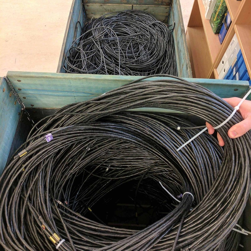
Large sensor wiring setups can make manual channel tracking and sensor identification very difficult |
Does TEDS affect sensor performance?The TEDS chip does not negatively affect sensor performance. The chips themselves are extremely small and add very little mass. In cases where sensor mass matters or the sensor is physically very small, such as miniature accelerometers, the chip can be integrated into the connector rather than the sensor body. As mentioned earlier, in Type 1 devices the same analog signal line is also used for TEDS communication. However, this does not affect the sensor signal because the TEDS chip is only accessed during setup, not during actual measurement acquisition. |
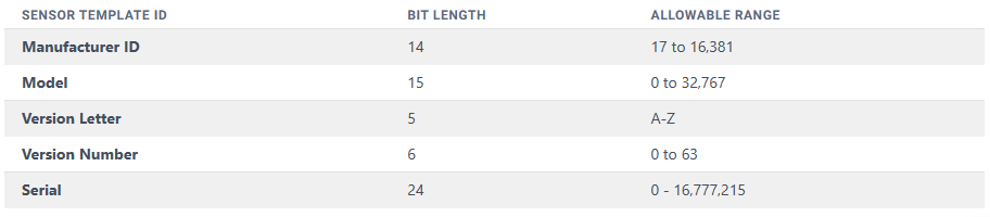
What information can be stored in a TEDS chip?The TEDS standard defines several categories of information that can be stored on the chip, as well as a number of templates used for different sensor types and calibration data. The four main categories of TEDS information are:
|
|
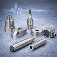
What sensors can be equipped with TEDS?In principle, any sensor can be equipped with TEDS. It is true that some sensors are too small to accommodate an EEPROM internally, or that the extra mass could affect performance. Some sensors are also designed for environments where the EEPROM cannot survive inside the sensing element. However, in these cases the EEPROM can be installed in the sensor connector or cable rather than inside the sensor itself. This makes TEDS practical even for very small accelerometers and for devices such as strain gauges. At the same time, there are situations where adding TEDS may not be necessary. For example, if you are using a very common thermocouple in a simple test, the benefit may be limited. The beauty of TEDS is that you can apply it in the way that best suits your sensors and your test environment. Your system can contain any combination of TEDS and non-TEDS sensors. The most common TEDS-enabled sensors
These are just the most common examples. In reality, nearly any sensor can be adapted for TEDS use. |
|
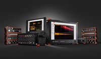
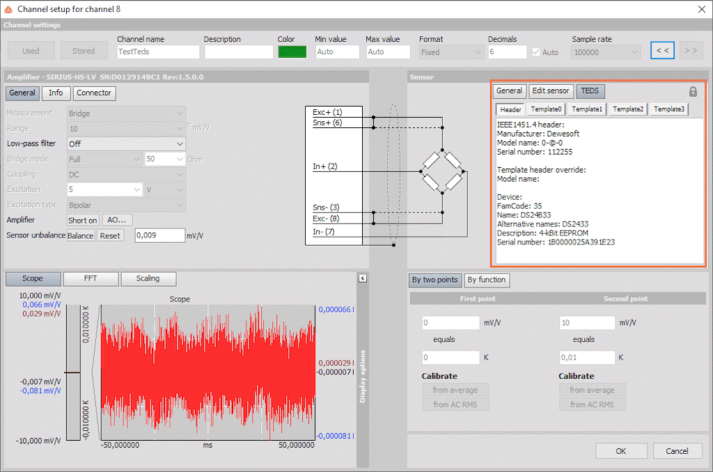
How does TEDS work in Dewesoft DAQ systems?The TEDS interface is enabled by default in DewesoftX, because TEDS chips are also used in Dewesoft DSI (Dewesoft Smart Interface) adapters. When a TEDS-enabled sensor is connected to a Dewesoft DAQ system, you can open the channel setup screen and immediately view calibration data, scaling, serial number, and other key information. This eliminates the need to consult paper documentation and reduces the risk of confusing one sensor with another. More importantly, DewesoftX can automatically populate the setup using data from every TEDS sensor connected to the system. |
Channel setup screen in DewesoftX showing TEDS information |
|
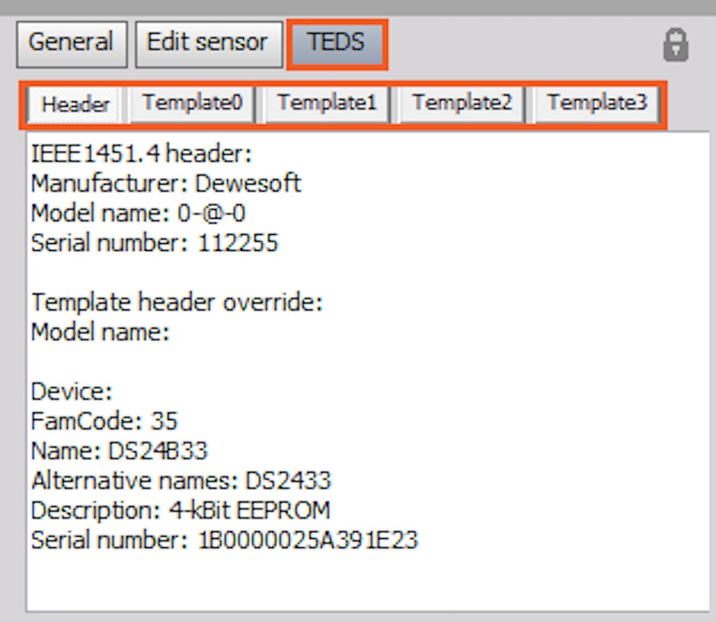
Dewesoft smart sensor technology based on TEDS Extending TEDS by storing DAQ signal conditioning settingsDewesoftX DAQ software does more than simply recognize the sensor and apply scaling. It matches the detected sensor with its internal database and can automatically configure the DAQ hardware according to that sensor’s required settings. This means Dewesoft’s TEDS implementation goes beyond simple signal identification. It also stores and restores signal conditioning settings such as range, input type, filters, excitation voltage, and other amplifier parameters. Other vendors have attempted this with proprietary templates. Dewesoft preserves compatibility by first writing the standard TEDS template so the sensor remains usable with any compliant DAQ system, then writing additional templates that allow Dewesoft systems to recall all relevant signal conditioning settings automatically. |
|
|
Multiple templates in the TEDS section |
You can edit sensor information by clicking the lock icon in the upper-right corner of the TEDS section. Test managers can also define passwords to restrict who is allowed to write data to the TEDS chip. Changing engineering unitsYou may wonder whether TEDS locks you into the engineering units originally defined by the sensor manufacturer. For example, you might prefer to work in [g] instead of [m/s²], or use °F instead of °C for temperature. This is not a problem. Although DewesoftX is built around standardized SI units, the software allows convenient switching to alternative engineering units through a drop-down menu. You can save that choice into the template so the same unit will be applied automatically in the future. Dewesoft fully implements the TEDS standard, while also extending it with signal conditioning settings that enable highly automated channel setup. |
|
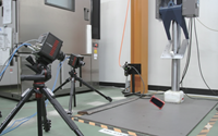
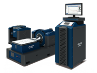
Marine performance testing and simulation |
TEDS case studyRoberto Basti, head of the Measurement Laboratory at the Institute of Marine Technology Research in Rome, Italy, has extensive experience with TEDS and with Dewesoft DAQ systems such as SIRIUS and DEWE-43. He explained that their workflow changed significantly once they adopted TEDS. In the past, calibration data had to be supplied manually to field engineers. Now that same information can be stored directly inside the sensors, allowing engineers to focus on the test itself rather than on calibration parameters. |
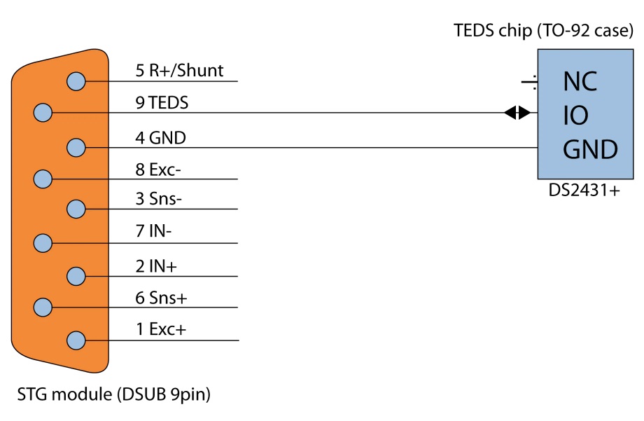
Can I add TEDS to my non-TEDS sensors?In one word: YES. Small TEDS chips are readily available, such as the Maxim DS24B33, and provide enough NVRAM to store both standard sensor information and amplifier settings. The Dewesoft STG signal conditioner has a dedicated TEDS input line that can be connected directly to the chip. |
|
|
TEDS chip setup for use with a Dewesoft STG module |
In most cases, it is best to install the TEDS chip inside the connector rather than inside the sensor body. For example, a strain gauge is essentially a thin foil element, so placing the chip in its DSUB connector is a much more practical solution. The chip can be programmed with sensor information using DewesoftX or the free TEDS editor available from Dewesoft. |
Advantages of TEDS
|
SummaryTEDS is a powerful and highly practical technology, especially when working with large numbers of sensors. It removes much of the tedious manual channel and sensor setup, saving time, lowering cost, and reducing human error. It is a proven, open, cross-platform standard supported by many sensor manufacturers and DAQ vendors. TEDS support is built into DewesoftX and is available across the Dewesoft product range. |